
Radar Launch Monitor Distance: Mark the Ball and Unit
For Radar Launch Monitor Distance, measure from the monitor’s specified sensing reference point to the ball’s resting position, then measure the ball to the impact screen separately. Mark both positions on the floor, align the unit with the target line, and follow the spacing and ball requirements for your specific model.
Key Takeaways
- How do you measure the distance between the radar unit and the ball? Measure from the manufacturer’s reference point on the unit to the ball’s normal address position, in a straight line along the target line.
- Does every radar launch monitor need a marked ball? No. Requirements depend on the monitor and the measurement: the Rapsodo MLM2PRO requires approved RPT balls for spin rate and spin axis, while Garmin Approach R10 supports Titleist RCT balls for spin rate.
- How much room does a radar setup need? Add the unit to ball distance to the ball to screen distance, then budget separately for the unit’s rear clearance, screen structure, and safe swing space.
- Can radar work with limited indoor ball flight? It can record shots, but short flight may limit the information radar can capture directly and affect some derived readings.
- What should you mark? Mark the unit’s position and the ball’s hitting position on the floor. Those marks help keep setup geometry consistent between sessions.
- We explain the basic room planning in our home golf simulator setup guide.
Free Printable Worksheet (PDF)
Print or save the one-page companion to this guide: Doppler Radar Unit-to-Ball & Ball-to-Net Spacing Spec Sheet. It collects the key tables and the checklist from this article.
Related guides
How Radar and Camera Launch Monitors Track a Shot
A radar launch monitor sends a Doppler radar signal toward the ball and reads changes in the returning signal as the ball moves. From the captured launch and flight information, the device reports or calculates metrics such as ball speed, launch direction, spin, and carry.
A camera based launch monitor uses high speed images of the ball and club around impact. This approach, also called photometric tracking, can suit a room with limited ball flight because the cameras observe the strike close to the hitting area rather than relying on a long stretch of visible flight.
Examples of radar systems include the Garmin Approach R10, the Rapsodo MLM2PRO, and the FlightScope Mevo+. Camera based options include Bushnell Launch Pro, SkyTrak+, and Uneekor EYE MINI.
Placement questions for Bushnell Launch Pro and SkyTrak+ differ from radar setup: these camera based units work around the hitting area, while radar systems are usually positioned behind the ball. Match the device to the room and the specific data you want to practice with, not just the label on the technology.
Measure the Unit to Ball Distance Correctly
Measure from the unit’s specified sensing reference point to the ball’s normal position on the tee or mat. Use the model’s setup instructions to identify the sensing reference point for measurement.
Put the ball in its usual hitting position and mark that spot on the floor with removable tape. Mark the radar unit’s position in the same way, then measure between those marks along the target line.
This gives you a repeatable unit to ball distance. It is different from the ball to screen distance, which starts at the ball and ends at the face of the impact screen, and different again from the full room depth.
| Radar model | Unit to ball placement | Ball to net or screen guidance | Combined minimum monitor to screen span |
|---|---|---|---|
| Garmin Approach R10 | 6 to 8 feet behind the ball | At least 8 feet | At least 14 to 16 feet before additional clearance |
| Rapsodo MLM2PRO | Follow model placement guidance | Follow model placement guidance | Follow model placement guidance |
The combined spans above add the stated unit to ball placement to the minimum ball to net distance. They describe the distance from the monitor position to the screen, not the total room depth or a safe player to screen distance.
Marking the Ball, Unit, and Hitting Position
Use floor marks to preserve the positions of the radar unit and ball. A short line of tape at each location is enough to show where the equipment belongs and where the ball should sit for repeatable shots.
Ball markings are a separate issue. A marking is required only when the model and the selected measurement call for a specific pattern or ball type; an arbitrary line or dot does not automatically meet that requirement.
The Rapsodo MLM2PRO uses radar and two optical cameras, and approved RPT balls are required for its spin rate and spin axis measurements. Garmin Approach R10 supports Titleist RCT balls for spin rate.
Keep ball markings distinct from club face stickers. A club sticker may support club data on a compatible system, while a ball pattern supports ball tracking; neither should be treated as a universal requirement across all monitors.
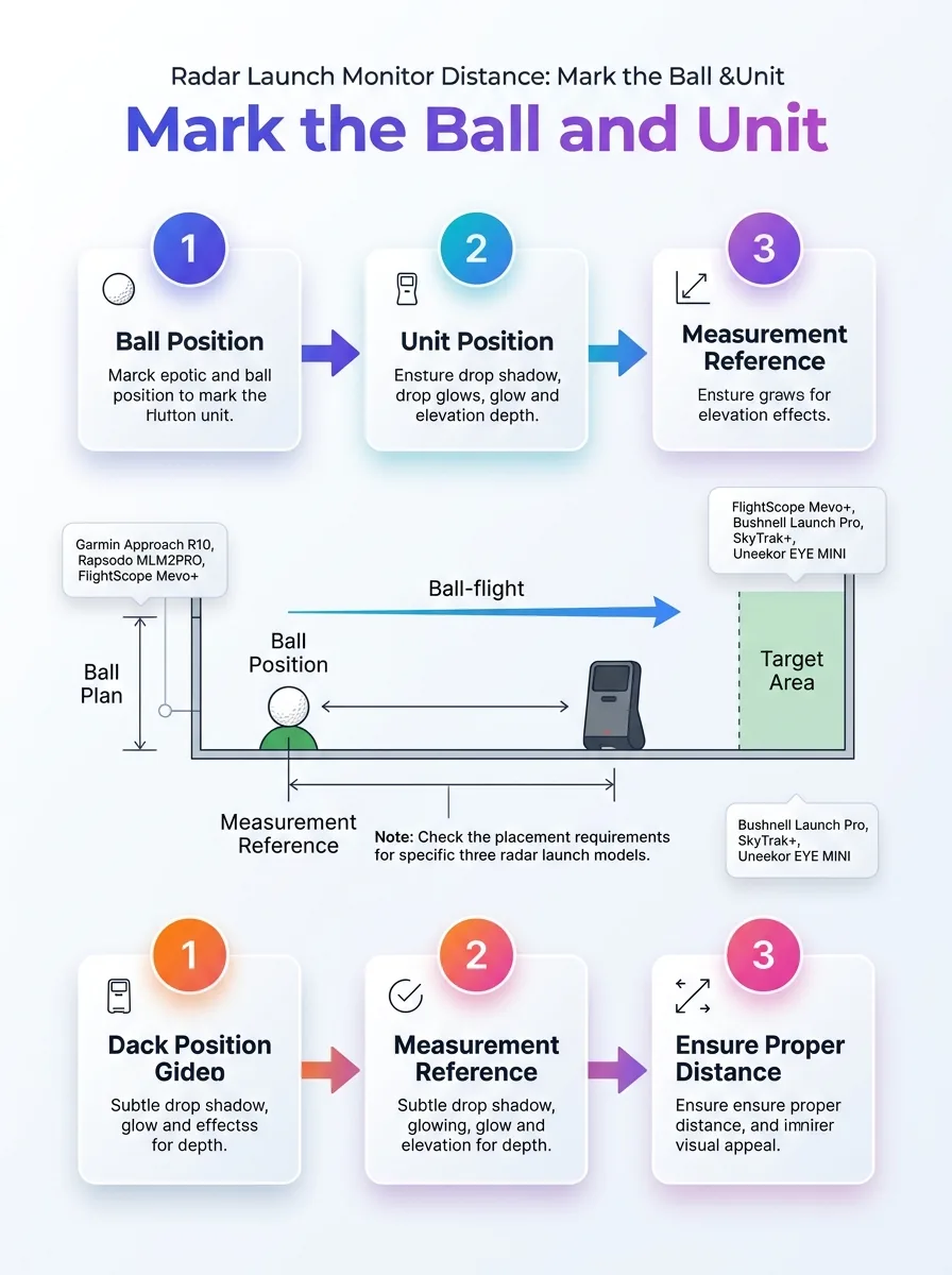
This infographic shows how to mark the ball and unit when measuring radar launch monitor distance.
Ball Flight Space and Indoor Radar Readings
Radar needs a clear view of the ball moving away from the hitting area. Limited indoor ball flight can reduce the information available for some readings, especially when a metric depends on observing the ball after impact.
The 10 feet of flight rule is a practical benchmark discussed for indoor radar use, particularly with FlightScope Mevo+ and Garmin Approach R10. It refers to meaningful early ball flight, not the distance from the radar unit to the ball; use the specific model’s setup instructions to determine its actual spacing needs.
Garmin’s stated R10 indoor setup calls for 6 to 8 feet behind the ball and at least 8 feet from the ball to the net. For the Rapsodo MLM2PRO, follow its setup guidance for the distance from the device to the ball and from the ball to the net.
When the room is short, check the device’s indoor mode, the selected measurement settings, and which outputs are measured versus calculated or modeled. Compare the same club and ball under the same setup, since a changed ball, moved monitor, or shifted hitting position can make readings less consistent.
Our guide to launch monitor metrics explains why a number can be directly measured on one system and calculated on another. That distinction matters when you interpret data from a short indoor flight.
Calculate Room Depth Without Confusing the Distances
To estimate the required room depth, start with the unit to ball distance and add the ball to screen distance. Then account for space behind the radar unit, the screen and its frame, and the clearance needed for a safe stance and swing.
| Planning measurement | Example calculation | What it tells you |
|---|---|---|
| R10 unit to screen span | 6 to 8 feet + at least 8 feet = at least 14 feet, with the minimum rising to 16 feet at the farthest placement | Monitor position to screen, before other room allowances |
| MLM2PRO unit to screen span | Follow model placement guidance | Use model guidance for unit and ball to screen spacing |
| Total room depth | Rear clearance + unit to ball + ball to screen + screen structure | Room boundary to room boundary, with safe use space included |
For example, a monitor to screen span of 14 to 16 feet does not mean a room with that exact depth will work. The unit needs space from the rear wall, and the screen frame and impact area occupy space beyond the screen face.
Also check room width and ceiling height. A golfer needs room to stand and swing without striking walls, lighting, or equipment, and left and right handed players may need different hitting positions.
Align and Level the Radar Unit
Place the unit on the target line, with its aiming direction set toward the same target as the ball. Keep the monitor steady and level according to its instructions, and position it at the required height relative to the hitting surface.
An off line unit can read a shot against a different direction from the golfer’s intended target. A tilted or shifted unit can also change the geometry the monitor uses, making shot to shot comparisons less reliable.
After alignment, hit a small group of shots with one club before changing anything. If the unit has moved, return it to the floor marks and repeat the alignment rather than adjusting the ball or aim to compensate.
When Camera Based Tracking Fits a Room Better
A camera based launch monitor can be a better fit when the room cannot provide the ball flight space required by a radar model. Because camera systems observe the strike near the hitting area, they can reduce dependence on long indoor flight, although they still need correct placement, lighting, and a suitable hitting zone for their particular model.
For readers weighing a photometric vs radar launch monitor, begin with room dimensions and the metrics you care about. We cover several systems in our launch monitor guides and comparisons, including models that use different tracking approaches.
Changing from right handed to left handed use does not automatically mean the radar unit must move if the ball remains in the same position and the target line stays the same. If the hitting position shifts, reset the unit to preserve the model’s required distance and alignment.
Radar Launch Monitor Setup Checklist
- Read the setup instructions for the exact monitor and operating mode.
- Identify the unit’s official measurement reference point.
- Mark the radar position and the ball position on the floor.
- Measure unit to ball and ball to screen as separate distances.
- Align the unit to the target line and level it as directed.
- Use the required ball pattern or type for the data you want to capture.
- Plan room depth, width, screen structure, and swing clearance separately.
- Test the setup with one club and a consistent ball before comparing results.
See also: launch monitor buying guides, outdoor launch monitor range conditions.
Summary
Accurate Radar Launch Monitor Distance setup starts with clear reference points: the monitor’s sensing position, the ball’s hitting position, and the impact screen. Keep those measurements separate, mark the positions on the floor, and follow the individual monitor’s placement and ball requirements.
For a home simulator, calculate the full room depth only after accounting for radar placement, ball flight, the screen assembly, and safe swing space. That gives you a setup that is easier to repeat and better suited to the room you actually have.
Frequently Asked Questions
Should I measure to the radar unit’s casing or its sensor reference point?
Measure from the point the manufacturer designates as the origin to the ball’s address position.
Does indoor mode remove the need for ball flight?
No. Indoor mode cannot extend the ball’s visible flight.
Can I move the tee between sessions and keep the same radar marks?
Yes, if the tee returns to the same spot; otherwise, recheck the monitor’s distance and alignment for the new ball position.
Can two golfers use the same radar setup?
Yes, when both golfers can share a ball position and have enough room to swing safely.
What should I do if readings change after I move the mat?
Pause comparisons until the mat, monitor, and ball are back in their intended positions.
Download the Companion Printable Sheet (PDF)
Print or save the one-page companion to this guide: Doppler Radar Unit-to-Ball & Ball-to-Net Spacing Spec Sheet. It collects the key tables and the checklist from this article.
Published by Launch Monitor Pro, a publication of Viking Trading Group LLC.
Related reading: then set ball position using the indoor launch monitor setup guide.